Toshiba G7 Low Voltage Severe Duty Industrial Drive
Toshiba Updated: 2007-07-17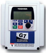
Whether your requirements are a DC drive application or a new AC installation, the G7 Series PWM Adjustable Speed Drive is the clear choice. The G7 Series provides flux vector technology with or without using encoder feedback. It is engineered to offer tight control over both torque and speed while offering the industry’s most user-friendly operator interface. Designed to handle the most demanding conditions, the G7 drive continues to be the best choice in the industry for the most demanding applications.
G7 Standard Specifications
Model Range 1 - 150 HP 1 - 350 HP 1 - 15 HP 20 - 300 HP
Voltage Rating 200 - 240 V 380 - 480 V 520 - 600 V 520 - 600 V
Input Voltage Tolerance ±10% ±10% +5% / -10% ±10%
Voltage Regulation Main Circuit Voltage feedback control (automatic regulation, 'fixed' and 'control off' selections)
PWM Carrier Frequency Adjustable between 0.5 - 15 kHz (ASD specific, consult factory)
Control System Sine Wave PWM System- Flux Field Current Vector Control
V/f Pattern Open Loop Vector, Closed Loop Vector, Constant Torque, Variable Torque, Auto Torque Boost, Manual Torque Boost, 5-point V/f custom curve setting
Overload Current Rating 110% continuous, 150% for two minutes up to 100 HP, consult factory for ratings above 100 HP
Frequency Setting Rotary Encoder integrated into EOI, 0 - 10 V, + -10 V, 4-20 mA, Binary Input, Motorized Potentiometer Input
Frequency Precision Analog Input ±0.2% of the maximum output frequency, Digital Input ±0.01% of the maximum output frequency
Frequency Command Resolution 0.01 Hz Operation Panel, 0.1 Hz Analog Input, 10 to 12-bit A-D Converter
Output Frequency Range 0 - 299 Hz
Speed Regulation Closed Loop (0.01%, 1000:1 speed range), Open Loop (up to 0.1%, 60:1 speed range)
Torque Setting ±250% of the Rated Torque
Torque Regulation Closed Loop (5%, ripple < 2%, ±100 range), Open Loop (10%, ripple < 3%, 50% to 100% range)
Discrete Input Terminals Eight Discrete Input Terminals programmable to 68 functions. The number of terminals may be increased using optional hardware.
Analog Inputs One 4 - 20 mA, one ±10 V and two 0 - 10 V (one of which is commonly used with a potentiometer)
Discrete Output Contacts Three Output Contacts programmable to 60 functions
Analog Outputs Two 4 - 20 mA/0 - 1 mA outputs programmable to 33 functions
Signal Isolation Optional Three-Channel Signal Isolation for 4 - 20 mA input and the AM and FM outputs rated at 750 V
Control Board Communications Ports RS232/485 and TTL Ports standard
Power Terminals Input (L1, L2, L3), Output (T1, T2, T3), DCL (PO, PA), DBR (PA, PB), DC BUS (PA, PC)
Set Point Control (PID) Proportional Gain, Integral Gain, Feedback Settings Upper / Lower Deviation Limits, Feedback Source Delay Filter, Feedback Settings Differential Gain
Control Power DC Bus Control-Power for units up to the 6750B, allows control power ride-through during momentary power loss
Protective Functions Fault input and outputs are fail-safe configured. Fault codes include: Overcurrent, Overvoltage, Heatsink Overheat, Load-side Short Circuit, Load Side Ground Fault, ASD Overload, Overcurrent During Start-Up, EEPROM Error, RAM Error, ROM Error, Communications Error, Armature Short, Auto-Tuning Error, Dynamic Braking Overcurrent, Dynamic Braking Resistor Overload, Emergency Stop, Undervoltage, Overtorque, Open Output Phase, Motor Overload, Loss of Feedback
Retry ASD can clear fault upon trip automatically. Programmable to 10 times with wait time up to 10 seconds between retry
Restart ASD will catch a freewheeling motor smoothly.
Ambient Temperature: -10 to +40°C, 14 to 104°F, Humidity: 95% non-condensing
Installation NEMA 1
Electronic Operator Interface (EOI)
LCD EOI (Liquid Crystal Display / Electronic Operator Interface) 240 x 64 graphics capable, back-lit LCD can display multiple parameters simultaneously. Keypad may be operated from an external power source. Software is flash upgradeable.
LED Indications Run (Red) / Stop (Green), Local / Remote (Green), DC Bus Charge Indication (Red)
Keys Local / Remote, Monitor / Program, Run, Enter, ESC, Stop / Reset, Up, Down
Rotary Encoder Encoder with Integrated Enter Key for Frequency Setting and Parameter adjustments
Monitoring Main Display shows two monitored items or can display up to 45 user-selected scrolling items including: Terminal Input / Output Status, Forward / Reverse, Frequency Setting Value, Output Frequency, Output Current, Output Voltage, Input Power, Output Power, Torque Current, Past Faults, Excitation Current, DBR Overload Ratio, ASD Overload Ratio, Motor Overload Ratio, PID Feedback Value, DC Voltage
Selectable Display Units Completely configurable along with Scaling Factor Multiplier, Current Display selectable between Amps or %, Voltage Display selectable between Volts or %
EOI Communications Ports RS232/485 and TTL Ports standard
Remote-Mount Display Remote mountable up to 1000' away from the ASD
G7 Engineering Specs
7-Series 120V Discrete Input PCB Manual
7-Series Conduit Plate Manual
7-Series Keypad Extender Cable Manual
7-Series Manual Speed Search Option PCB
7-Series RTC Installation Manual
7-Series Serial Communications User Manual
7-Series Simulator Installation Manual
7-Series Terminal Isolator Installation Manual
G7 ASD Operation Manual
G7 ASD Quick Start Guide
G7 Applications Workbook
G7-French Quick Start Guide
G7-Spanish Quick Start Guide
Related Manuals
Toshiba G9 Low Voltage Severe Duty Industrial Drive
Toshiba H7 Low Voltage Standard Duty Industrial Drive
Toshiba HX7 Low Voltage Standard Duty Specialty Drive
Toshiba Q7 Low Voltage Variable Torque HVAC Drive
Toshiba S11 Low Voltage Standard Duty Micro Drive
Toshiba nC1 Low Voltage Standard Duty Micro Drive
Toshiba G3+ Low Voltage Severe Duty Specialty Drive
Toshiba AS1 Low Voltage Standard Duty Integrator Drive
Toshiba W7 Low Voltage Variable Torque Water/Wastewater Drive
Toshiba T300MVi Medium Voltage Standard Duty All Purpose Drive
Toshiba MTX NEMA 3R MV Severe Outdoor Drive
Hitachi SC-OPE 3H/3I Operator Interface and Networking Devices